The people who have the creativity to truly fabricate a FWD car to a RWD car are impressive. But even more when the engine is mid mounted!!!.
I found this on Build threads: http://www.build-threads.com/build-threads/mid-engine-rwd-turbo-crx/
and here: http://honda-tech.com/welding-fabrication-53/my-mid-engine-rwd-turbo-crx-2609439/
Simply Amazing!!!
Mid Engine RWD CRX turbo!
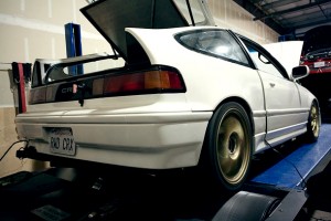
It seems the there are many members of the Honda fraternity who still undeniably love the marquee, yet are quite bored of the whole FWD thing. On this website alone there are 3 other builds documenting Hondas being DIY’d away from their standard drivetrain layout. There’s a front-engine RWD F20C CRX, a mid-engine rear wheel drive DC2 Integra, and an AWD Twin Engine Del Sol. This latest build uses a mixture of those combinations, giving us a mid-engine rear wheel drive CRX. Honda, are you listening?
Thanks to Daniel for submitting.


I found this on Build threads: http://www.build-threads.com/build-threads/mid-engine-rwd-turbo-crx/
and here: http://honda-tech.com/welding-fabrication-53/my-mid-engine-rwd-turbo-crx-2609439/
Simply Amazing!!!
Mid Engine RWD CRX turbo!
It seems the there are many members of the Honda fraternity who still undeniably love the marquee, yet are quite bored of the whole FWD thing. On this website alone there are 3 other builds documenting Hondas being DIY’d away from their standard drivetrain layout. There’s a front-engine RWD F20C CRX, a mid-engine rear wheel drive DC2 Integra, and an AWD Twin Engine Del Sol. This latest build uses a mixture of those combinations, giving us a mid-engine rear wheel drive CRX. Honda, are you listening?
Thanks to Daniel for submitting.
The next step for my planned mid engine conversion
was to find a doner vehicle's front core support to use as a jig to line
everything up in the back of the crx. I was blessed in the form of a
FREE 1990 civic 4door from a friends back yard, as long as I agreed to
take the rest of the car to the junkyard. A fun and sawzall filled afternoon with from friends produced the desired result of front core support including, suspension, motor mounts, front crossmemember, some 13's for a later burnout, and even a d15 I threw on the ground...
   the junkyard was a little confused when I brought this in, Ha ha 
|
|

|
| #16 | |||||||||||||||||||||||||||
my plan for getting the rear suspension streight in the car was relatively simple.
1) Level the car, and measure the center point of the stock rear suspension with plumb bob, and the fender gap at the desired ride height.  The doner core support was completely stripped down to the bare minimum. the steering rack was removed in favor of small 1/8' steel brackets to hold the stock tie rods straight, and as much excess metal was cut off as possible for weight savings. I was aiming more to use to core support only to line everything up, and not so much to be structural.    2) I then figured out at what point in the suspension travel of the stock front end the axles were as straight as possible. I took a spare set of front shocks and installed them on the core support and welded them solid in this position. this might be used as stiff drift suspension later (joke) 
Once the core support was prepped and ready to install, It was time to cut out all the stock rear suspension, gas tank,
brake lines etc and make a huge hole in the floor big enough to fit the
core support into. I had wait a few days to do this until the car
finished passing smog...
 No turning back now...   
|


So now that the motor is sitting in the car, I started the long
process of wiring. the first step was to remove ALL of the stock crx
wiring. Because i planned on only having this car as a drag car, every
inch of stock wiring was taken out (except for leaving a few behind for
tailights and headlights). I also was going to use completely OBD1
wiring colors, sensors, ecu(hondata)
etc. my goal was to make all of the wiring as SIMPLE as possible, with
all unnecessary things removed...this was about the time that I pulled
the dashboard, all the vents, heater, stock fuse box etc, and preformed "stage 10 weight reduction" on the interior.
 I used a stock ex harness from an EG for the engine harness, then chopped off the matching plugs, as well as the fuse box to make the crx side of things. whenever possible, I tried to maintain standard OBD1 colors, plugs, etc for ease of future modification or replacement of parts. I separated all the wiring that I would have to complete into a few categories before i started, and attacked each group one at a time. I built an aluminum control panel, with 3 main controls. A master switch, ign switch, and starter button. both the master and IGN switches were wired to terminal board, to make later connections easier. also visible in this later picture is the high/low boost switch, and a set of annunciator warning lights (aviation influence) for oil pressure, check engine, charge system, etc.  after hooking up all of the power, ground, and misc wiring associated with the main relay, hooking up all of the sensors was not really difficult, but more time consuming to make check and double check every wire. interestingly, the stock 89HF harness contained every color that i needed to copy the 92-95 scheme. 
Last edited by zimsplat; 07-28-2009 at 11:23 PM. |
|
|
|
| #66 | |
I had planned on totally gutting the car including dash and stock
gauges, but then I started to have second thoughts. I had a friend that
got into trouble for removing the stock VIN number on the dash, so I
decided instead to keep a "dummy" dash in the vehicle. I cut out all the
unnecessary plastic parts from the underside, leaving only the top
shell of the dash. After doing this, I started to wonder how difficult
it would be to make the stock gauges with tach and water temp gauge
work with the all OBD1 wiring. a little tinkering, and I had both
working great. I also modified the stock HF green shift up light to work
with Hondata. The only other thing that I was missing was a
speedometer.
 The stock crx gauges work with a cable driven speedo. first of all, there was no way I was going to find a cable long enough to make it work. second of all, I used a hydrolic transmission with the electronic speed sensor. I noticed that the speedo from a DX 94 civic was about the same size as the crx one...  So with a little modifying with a dremel tool, I had it fitting nicely   Plus some trustly shoe goo to hold it in place  Most people look right past the "stock" looking gauges :-) 
|
|
|
|
| #67 | |||||||||||||||||||
Also under the dash, there was another major project to be completed.
I wanted to change the car completely over to a hydraulically activated
clutch. I figured if i could mount a master calendar on the inside of
the firewall, i should be able to use the stock clutch pedal.
So i fabbed a quick bracket and drilled a hole in the top of the pedal.
I ran some hard lines back to where the firewall would soon be, and
hooked it up temporarily to check the pedal effort and travel.
 works flawlessly!   reservoir access please ignore the wad of headlight wires. I had to jimmy rig them to get home from the drag strip one night and havn't fixed them since!  looking from the front core support back. the fuel feed and return lines, as well as the walbro 255 external fuel pump. on the far right is the hardline for the brake booster 
    gas door cold air intake mod :-)  
the motor was a little floppy in the engine bay, so i stiffened it up by building a 1/4" steel plate front mount. its SOLID now
  
 Random fusebox and main relay detail   Ecu mounting  under the "dash"  I used a tandem bike shifter cable to extend the throttle cable 
  
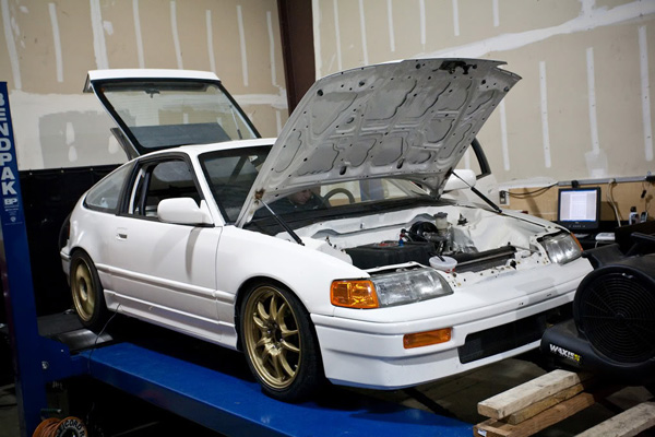
Hey, new build has started! car has gotten stripped back down to prep for paint and new motor setup.
Ive also been doing some work on the suspension to stiffen it up and
hopefully make a little more stable at high speeds. Ive been fabbing
traction bars with heim joints to replace the stock radius rod bushings that are totally worn out. Also got some new stiffer springs, and koni yellow shocks for all 4 corners.
Finished my front suspension today, should be much less flexy than stock.
 Started sizing up and building brackets for the rear also 
Updates....
Quarter panel is still going places  Getting very tired of stripping off spay-paint  So I bribed a few of my friends to help out Jeff  made a nifty gas strut to hold the engine cover open 
It needs to fit through this hole...   sexy bends :-)   Lol who votes this is the end of the exhaust fabrication?? I'll probably put some sort of muffler on it. in this pic you can also see the water lines for the intercooler, engine coolant lines in progress, fuel lines as well as hardline to the brake booster
did some tinkering on the car the last few days.
got the intercooler and charge pipes all figured out. Short!!   built the coolant lines  Wintertime around here sucks! We had some good weather so Ive been trying to get all of the things that require me to lay under the car finished
New and improved shift linkage
 transmission front mount 
Oh by the way, some pictures of new brakes.
Car now has 11.1" redrilled prelude front rotors with 17CLVN calipers from an acura ledgend with DA knuckles. previous civic EX front brakes have been moved to the rear. I also modified a DA with ABS 1" master cylendar and booster to fit. IT stops VERY well now, but now all of my alignment needs to be reworked before  after  front brake comparison 
I'll be brutally honest. I hate asian cars. I've come across a few that I have looked at, but overall I don't like the way they look or sound. Hollywood and 16 year old ricers
have not helped me along any. I'm purely a muscle car enthusiast, so
this may be the only time I ever post on an import forum, but I want you
to know that I for whatever reason have always had an unusual (for me)
appreciation for the CRX,
and I read all 26 pages of this thread. I wondered if someone had done a
mid-engine conversion to one, so I googled it, which lead me here, and
now I know. Congrats on the mag cover story btw. I will have to pick it
up off the rack next time I'm at the store. There are a few suggestions
I'd like to make though if you don't mind. If you do a more streetable
version 3, what I would do if it were mine would be to see if I could
fit a gas tank
in the center hump where your coolant lines are currently run. I own a
Fiero, and that's where the tank is from the factory. The coolant lines
are then tucked behind the sideskirts.
Battery would be up front with the old engine bay converted to a trunk.
Other mods I would do would be to put a vent in the hood to let out hot
high pressure air. Many Fiero owners do this to improve handling as it
keeps the car from floating at high speed. The gas
door intake was ingenious, but I think V3 should be more professional,
like the car came that way from the factory. I would shave the gas door lid and either put scoops on the quarter windows or go with lower quarter panel scoops. I would also cut the rear hatch
window in an inch or two on the sides and put full length vents running
down to let hot air out of the new engine compartment. Because many
exotics also showcase their engines this way, I wouldn't bother covering
the motor up with an aluminum sheet so spectators can see it in all its glory under the rear glass.
Instead I would separate the passenger compartment with a piece of
Lexan running from the roof down halfway where it would meet the
firewall. I have seen this in a few exotics as well. Lastly, I would
probably go with small block Chevy
or at least a GM 3.8SC, but that is the muscle car guy in me talking. I
know you all have your own ways to getting power. I'm no fabricator, so I
don't know what it would take to do all this, or if some of it would be
legal on the track, but I thought there would be no harm in putting it
out there. Hope I didn't hijack your thread and ramble on too much. I
wish you the best of luck. Please keep building because I hope to read
more on this project later and it's just pure awesome!!!
  [IMG]  [/IMG] [/IMG]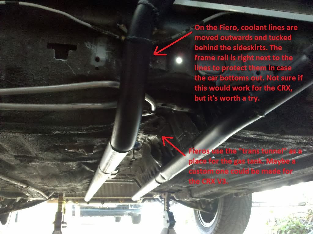  |


 3
3


Comments
Post a Comment